During my work
I realized
that despite at European level
there are a number of regulations
today again
there is a great distinction between the various hooks
that can be used
in a plastic
there are short hooks
the normal eye hooks
an infinite series of conductive hooks
Already only in normal eyelet hooks
there are 3 different types
I do not want to divulge
if you want I will do a separate video
but this is a separate speech
in the light of all these differences
I was therefore necessary
put me to check
that the various hooks were compatible
with hooks of different types
sometimes it happens that the same hook
so for example a short hook
like that of the hound
if acme carriages
and on rough carriages
despite the regulations require specific measures
for mechanical games
design differences
sometimes the hook door is not at the same height
and the same type of hook is hard to hook
What I asked myself
what is the fastest way
to test all the different types of hooks
in the most common conditions?
The most common conditions
at least in my case
I will use short hooks
Märklin / Trix
because they are the most suitable for telex hooks
and conductive hooks
in a separate video
I will put the link in the description
I had pointed out
that the conductive hook
RTS
it was not compatible with the digital Telex hook
and if it was successful
to insert the two hooks
mechanically forcing them
then the digital hook could not break off
so it could only be used as a transport
there are now some new hooks
conductors I'm starting to use
conductive hooks that are expressly Märklin
and no longer produced by another company
To test all these hooks
I therefore decided to group
the most important hooks
in a single rolling stock
to avoid always pulling some out of it
the Telex hooks were only on the Roco
on e412
I always had to get her out
to check the hooks
the conductive hook
it was either on the pilot carriage vitrains
or on e454
I always had to pull out one of the 2
so I told myself
it takes something
on which to mount both
something I can leave
out of the dust without getting damaged
and let me check
all the hooks I need
As?
use a carriage
along the lines of the carriage
present in reality
the carriage tests brakes
I decided to build
a carriage tries hooks
I will use
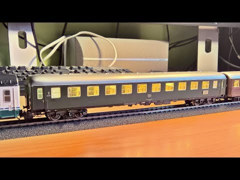
an old-fashioned carriage
it's a carriage
which I believe is a German UIC X
or rather, it's definitely German
but I think the model is very similar
to the Italian UIC X
to which at one extreme he will have
a current conductor hook
and on the other a digital hook
the digital hook
normally it would provide a decoder
in this case
in this case a button will be mounted here on the roof
that will allow
to check it manually
to cover then the original writings
we will also do the Decals
together, but it will be another video because it will be long
is...
Let's throw ourselves into the project!
To illuminate our carriage
since
originally, when I received it
he had an old incandescent lighting
that I have already removed
this one
we'll have to take it apart and remove it
bellows bellows
and then it will open
for six simple joints
at this point
since
I do not want to
connect anything to the roof
to be able to reopen it in a second time
I want to reuse
the same supports
of the original light
but going to put
a base for the LEDs
what do i want to do?
I want to insert
taking a piece of plastic from an electrical conduit
the channel is this here that I'll show you now
a classic electric channel
that you buy at Brico
you cut the upper part
that would be the riding hood
that goes to close it like this
and this part here is very flexible
and you can use it for different jobs
my intent will be to go
cut it to the right size
to be able to put it here in the middle
and then use this strip
as a base of support
for the led strip
doing so
we will go to support it
then in the original support
the best thing at this point will be to paste it at the highest point
let's try to see if the length is right
using the supports
that were already connected
to the original lighting
we'll go and place them here and here
Once the base is prepared
we can use any led strip
I have chosen to use this here
a normal 12volt strip
we're going to cut it to the right length
and then we'll have to paste it
as we have seen, the support is not perfectly centered
therefore it will be necessary to insert this led strip
a little 'moved on the inside
so I would say more or less like that
at this point we will then have to prepare
the system that will power
the whole
to prevent the light from being too bright
we will use a resistance
in this case from 1KΩ
but from 2 watts
to be sure
that does not warm too much
the resistance we are going to pay directly
on the feeding area
of 12 volts
Now, after entering the resistance
we're going to insert a diode bridge
right here
to which we will connect on one side
the resistance to the pin of +
because in this case we put it at the positive pole
and then to the pin of - a wire coming from the negative pitch
While we do this
we must also change
internal electrical connections
as I said
one of the hooks will be digital
so to do this
we will go to remove
the electric contact that was there initially
because we will not need it anymore
let's remove this little mollet
from its housing
this we will go to remove
in such a way as to make the rudder free without difficulty
and then we'll go and get this over here
the rudder works more smoothly
and we have also earned
this little clothespin that will be usable for other
once you've done this
let's go and put it back
the interiors that we will not modify
because it would not be worth it
and moreover the lighting will be mounted like this
to allow then
of having
the conductive hook
it will stick to this electrical contact back here
back here
and to the ski that will come from here in the middle
so we will have the diode bridge
placed as close as possible to these 2 contacts
at this point the difficulty will be
bring
the mass
bring the mass
up to here
so we will have to connect another electric wire
to bring it up here
to enable the electrical conductor hook
at this point there will be some usefulness
connect a wire
to respect the colors I will use a red
to that vertical electric contact that I showed you before
that contact through the clip
that in the other hook I removed
will bring current to the conductor hook
this hook
it will be both outgoing
then it will then be connected to the skate
and the shoe will feed both the lighting and the hook
and at this juncture instead
we will use it on entry
to try indoor lighting
we can proceed with a lighting test
As stated the purpose of this carriage
it will then supply
electricity through the conductive hook
even without having to pull each time out
a locomotive
or a carriage
equipped with a shoe and relay
at this moment the skate has not arrived yet
I started doing the jobs first
and let's see right away
how will the interior lighting be
it's not bad at all
having been positioned
not exactly in the middle of the support
but on the side also illuminates the area of the corridor well
and the effect is very nice
clearly the type of lighting used
it is from a past era
then a 3 or a 4
and therefore it is tending to yellow
on a more modern era
it would have been more correct
the use of a smears
with a bright shade
more Freda or otherwise more neutral
at this moment a buffer capacitor has not yet been inserted
therefore during the movement
presents very unpleasant flicker
to solve this problem
just enter
a buffer capacitor
at the other end of the strip
since one end is already occupied
to insert the diode bridge
and you will also need to clean the wheels a little
that being a used model anyway
they are not very clean
one of the things I do not like about this carriage
is that in intercommunicating
there is no glass
to solve this gap
I decided to employ
of the almost transparent plastic strips
that I cut from a plastic envelope for documents
that I will go to paste
with vinyl glue
exactly here
to make this effect
the effect obtained this here
of a kind of opaque glass
definitely better than the original
definitely
the glass effect
of a vintage carriage 3
where sometimes there were these glasses
not completely transparent
but opaque
at this point
in our project there is still one thing to do
that is, start putting the predisposition
for the digital hook
to insert the digital hook
I will use a very simple circuit
that will see the insert
between the diode bridge
and the hook
of a switch
I recycled from an old router
these here
which are normally open switches
what does it mean
that normally do not pass current
so our hook will remain unpowered
it will not have tension and will not heat up
when he must do the release test
because to get hooked as you know
you do not need to activate it
just press the button
and the hook being powered
the wagon will be released
I will go to this switch and insert it
in a hole directly above
it will not be beautiful
esthetically
but as I said this is a functional carriage
and that does not center anything with reality
to prepare the digital hook
we will go first and foremost to prepare
our switch
I glued it on a base
that was a base of an old skateboard
which will then be placed
above a thickness
a remnant of some kit
and it is biadhesive
I will cut it
and I will then go to place it
in this area here
this thickness here
so when I will press
the weight will be discharged above
and it will not make the whole strip flex
at the same time
it will be quite hidden
because the wires that will start from our switch
in reality they will be in a bathroom area
and therefore they will not be visible from outside
now as I said at the beginning of the video
the led strip has not been mounted
exactly in the middle
it was mounted all on one side
this to allow a uniform diffusion of light as possible
so I can remove a part of this strip
exactly where the switch will go
to allow the switch itself
to go and unload the weight
directly on this plastic part
as you can see
compared to video start
I moved the two supports
because I realized
that gave problems to closing the carriage
initially they were more external
and right here they were present
the parts of the roof mold
which therefore did not allow
the perfect closure of the carriage
positioning the supports in the center
it is true that here it will tend to bend a little more
at most, I will insert a support here
but the closure of the carriage is assured
the hole has been made
It did not come very clean but that's okay
I glued the thick I showed you under the base
now orienting it towards the Lao where the hook will be present
the button will position itself like this
then I will still have to go and pierce the upper roof of the carriage
to allow the button to exit
and that will be clickable from the roof
now I'm going to solder a capacitor
exactly where I have also soldered
the power points of the led strip
this to allow
to the strip to have a more stable lighting
to have a little autonomy
in the moment in which the power was missing
and to allow
to the digital hook to have a more stable lighting
this because
exactly on the opposite side of the strip
there are 2 other contacts
and I'll go get it from there
the current for the hook
the digital hooks work from 12 to 20 volts
this strip should be about 14
therefore I would like to use this strip as a means of feeding
to have a lower voltage that does not risk damaging the digital hook
now instead we will go to solder a soft thread
between one of our switch contacts
and the contact - of the strip
we will use a soft thread to allow the strip to keep moving
and we will go to pay it at -
because usually you prefer
intervene on the negative pole
rather than on the positive pole
this switch as mentioned is a normally open one
therefore in a basic state it does not let current flow
and this will only pass
when the switch is pressed
I mounted the digital hook
and the wires have made them pass under this axis
and following the thread of the mass they will then go up
both the threads are very small original ones
and do not suffer this kind of movement
on the opposite side I mounted the skateboard instead
that following his hole
then it will come out below
and it will be soldered directly to the diode bridge
welding here will mean
which will directly power both the conductive hook
that the diode bridge and all its users
the white thread
which can be taken as the +
it will be soldered directly
here on the + plate
of the led strip
while the black will be soldered
here on the switch
which will therefore allow to
to open it and make it work
only when requested
We have reached the moment of truth
all the wires are connected
and if I go to give power
our carriage lights up
now I did tension checks
and the 1kΩ resistance I put
the tension lowers me
which comes to the strip at about 8 volts
What does it mean?
it means that the LEDs will heat much less
because 12v on the normal stripes
made for example by 5050 LEDs
they heat up a lot
this here under these conditions will heat very little
the resistance being 2 watts
it does not heat almost
but there is one thing to say
when I press the switch
now it is hooked up with a Gran Confort carriage
and all is well
the digital hook works
when I activate it
this will consume a lot of energy
so in reality the interior lighting is turned off completely
But it works
so the switch works without problems
and the hook unhooks the wagon that is towing
the problem is when I activate it
going to take a lot of tension
this will turn off the lights
the diode bridge is not heating up
and not even the resistance
and the condenser
combined with a cleaning
made to the clothespin
it makes the lighting very stable
I would therefore say that the experiment was successful
and now we're going to see her in traction!
we are at the moment of the trial on track
and what's better
that a composition to try out the various types of hooks
present in what will be my rolling stock
we have between the locomotive
a German BR81
from a Märklin starter set
and the first car
the Roco PV Train
a relex hook on the locomotive
and a short hook Märklin on the wagon
between the Roco PV Train
and the MDVE Vitrains carriage
we have the same coupled
short hook on the roco wagon
and relex hook
borrowed from the locomotive
because that car there will then have a change
then we have the MDVE wagon
and the Carriage Try Hooks
a conductive hook
and the digital hook
we will check now if it is possible
disengage this type of coupling
with the new types of conductive hooks
on the opposite side instead
of the Carriage Try Hooks
we find the new conductor hook Märklin
coupled to the RTS hook
that right now
it is used on all my Corbellini coaches
being in curve
this type of operation becomes impossible
let's try on the straight
No, the digital hook
it is not yet fully compatible
with current conducting hooks
I reversed the MDVE
on this side there is a Relex hook
which can be seen as a normal eyelet hook
the coupling happens without problems
and also the release
same thing with the short hook
of Märklin
and the respective digital hook
the coupling happens without too many uncertainties
and the release takes place in an equally fluid manner
unfortunately the problem of lights
it can not be solved
unless you use a power system
independent only for the hook
because at the time of excitement of the coil
this absorbs a very high amount of current
which can even reach 90/100 MA
a strip of LEDs in comparison
in comparison it absorbs 50/60 MA
so we can understand why
at the time of activation
the lights come to extinguish
as soon as the switch is left
the current returns to the lights
and they are rekindled
Good! This video is everything!
Our carriage is complete
it works excellently
we only need to give it a more appropriate livery
compared to this German green that I really do not like
I will probably take as a starting point
the livery of the carriage tests brakes
but it will be a separate video
where we will do it together
it is good! That's all! Thanks for the mink!

Không có nhận xét nào:
Đăng nhận xét